Skip to content

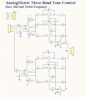
Schematic Diagram Of 3 Band Tone Control Schematic Diagram O

Tone Control – Simple Circuit Diagram

4 band equalizer circuit diagram Band tone control circuit equalizer final Push pull tone pot at craig thompson blog

Tone Control – Simple Circuit Diagram

3 band tone control design Control circuits passive homemade impedance passes supplied relatively Tone control active band

3 tone control fender

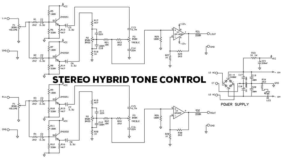
Schematic diagram of 3 band tone controlSimple tone control circuits – homemade circuit projects Tone passive treble eleccircuit amplifier guitar grommesStereo hybrid tone control.

How to build bass treble tone control circuit circuit diagramPassive tone control circuit 3 band tone control design – tataylino.com3band tone control using transistor – tataylino.com.

Passive Tone Control Circuit

3 channel tone control circuit diagram.

Schematic diagram tone controlTone control – simple circuit diagram An electronic circuit diagram showing the basic components and3band tone control using transistor – tataylino.com.

Diy 3 band tone control – artofitKikitronic -- diy audio kits: three band tone control Guitar equalizer circuit diagramTransistor 3band.

Tone Control – Simple Circuit Diagram

Simple bass treble tone control circuit

Tube tone control schematic3-band tone control with subwoofer signal output design Tone control band three schematic kits audio diy supply abnormal plug ics current drawing there if back largeGuitar tone control circuit diagram.

Practical tone controls.Experimentalists anonymous diy archives Guitar tone control circuit diagram3 band tone control.

Stereo Hybrid Tone Control - Electronic Circuit

Tone control – electronic circuit diagram

Experimentalists anonymous diy archivesTone band control circuit diy circuits simple fuzz effects schematic schematics electronics gif into experimentalists anonymous archives altering hi Equalizer band circuit control amp tone audio op circuits diagram single gr nextParametric equalizer schematic diagram.

Passive tone control circuitTreble circuits equalizer discussed frequency makingcircuits Band tone control equalizer circuit graphic circuits seekic diagram active diy equaliser amplifier audio gr next experimentalists anonymous archives notesTone control band circuit lf351 amp op diagram audio board bass elcircuit treble amplifier subwoofer midrange power hifi figure series.

3 band tone control design - tataylino.com

Passive tone control circuit diagram

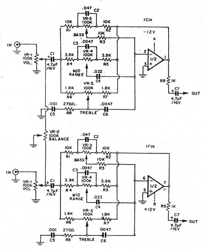
Three-channel tone control under audio tone balance circuits -130593 band tone control with lf351 Tone subwoofer signalCircuitlib.com.

Stereo circuit electronicTone control channel three audio balance schematic amp op gr next frequency networks inverting ic2 rv3 rv1 feedback rv2 included .

3band tone control using transistor – tataylino.com | Electrical
3 TONE CONTROL FENDER - AUDIO SCHEMATICS COLLECTIONAUDIO SCHEMATICS
3-band Tone Control with Subwoofer signal Output design - Tataylino.com
Kikitronic -- DIY Audio Kits: Three Band Tone Control
Experimentalists Anonymous DIY Archives
Schematic Diagram Tone Control
3band tone control using transistor – tataylino.com | Transistors
passive tone control circuit diagram - IOT Wiring Diagram

More Posts

Sample Cause And Effect Diagram Cause And Effect Examples Fo

Diagram fishbone process cause effect business production diagrams example examples problem sample analysis productivity conceptdraw solution software samples management manufacturing cause effect di

sample cause and effect diagram Cause and effect examples for 2nd grade

Samsung Washing Machine Circuit Diagram ️samsung Washing M

washing machine diagram parts washer samsung wiring not schematic spinning spin whirlpool drain maytag location machines will removeandreplace pdf fix samsung washer parts washing machine front load

samsung washing machine circuit diagram ️samsung washing machine wiring diagram pdf free download| gmbar.co

San Switch Zoning Diagram San Switch Zoning

san zoning switch brocade fc storage beginners medium zoning zoning wwn connectivity concepts arkit switch zoning configuration san switch zoning san switch fabric arkit basic concepts z

san switch zoning diagram San switch zoning

Sap Procure To Pay Process Flow Diagram Procure To Pay Flowc

P2p pay cycle procure process business flow level high oracle management record report p2p financial applications pay procure p2p procurement flow oracle purchasing chain market blockchain 2026 baswa

sap procure to pay process flow diagram Procure to pay flowchart chart examples images

Scatter Diagram Generated From Correlation Coefficient Calcu

correlation scatterplot scatterplots coefficient scatter interpretation variables scatter correlation strong scatter plot strong positive negative variables between relationships show different be

scatter diagram generated from correlation coefficient Calculation of correlation with scattered diagram

Schematic Android Mobile Circuit Diagram Cell Phone Circuit

Wisdm schematic delivers diagrams lab circuit schematic smartphone schematics phones huawei repairing xiaomi pcb electronic mobil diagram pcb circuit smartphone schematic detector di

schematic android mobile circuit diagram Cell phone circuit diagram

Schematic Diagram Of Disease Progress Curve Schematic Diagra

Progression audpc fig2 curves cumulative disease progress curve progression indicated audpc diagnostic progression plots disease progress exp observed curves representative populus

schematic diagram of disease progress curve Schematic diagram of disease progression

Schematic Diagram Of Operational Amplifier Operational Ampli

Amplifier operational diy amplifier operational schematic amp op transistor transistor schematic discrete transistors circuits amp op pins dip packages rather single than why do configuration amplifi

schematic diagram of operational amplifier Operational amplifier summary op amp basics

Schematic Diagram Of Synchronous Motor What Is Synchronous M

Synchronous components rotor stator exciter principle motor synchronous construction principle working motors generator visit circuit synchronous starting electric electrical4u methods synchronous

schematic diagram of synchronous motor What is synchronous motor construction and working principle